High voltage technology
There are several points to be considered in the application of piezoelectric membrane for vibration excitation. Because the impedance of capacitance transmitter decreases with frequency and approaches to infinity at low frequency, it may need higher voltage drive (usually several hundred volts), for example, full audio range speaker. Usually, the voltage is raised with a transformer to provide the required driving signal. In this case, there may be greater stress at the junction. First, a 100NF capacitor with a 2 ohm full circuit impedance is given to supply the 30V voltage. The initial current pulse peak is 15 amperes (assuming power supply capacity can reach this value). Such a current "peak signal" can expose defects on the connection point.
Next, we consider a transformer with a distance from 12V to 240V. A 200uA in the primary DC (DC) current (corresponding to the voltage applied to a 0.5V). When the circuit is open, it may cause 830V voltage surge in the secondary circuit, which is much higher than the expected 20 times amplification factor. Even with a large capacitive load, high voltage can be seen. Worse, if the secondary circuit is broken, a current pulse of over 10 nanoseconds of the 60A process will be generated. This is not a problem for a good joint. However, if some kind of lead connection can cause any bubbles, the reduced piezoelectric constant effect will cause breakdown. This event is disastrous, the familiar burst sound and the blue arc can be proved.
The answer is:
1) silver and ink electrodes are necessary - thin vacuum sputtering electrodes can not withstand high voltage.
2) the large area contacts reduce the stress. We apply the silver ink to the hollow rivet / rivet to obtain the additional conduction path of the film electrode.
3) (possibly) a semiconductor contact to reduce the current surge, which is equivalent to series resistance in the circuit. The actual value reaches 1K, Ohm will generate only the output loss of the decimal bit and reduce the peak value of the current.
frequency response
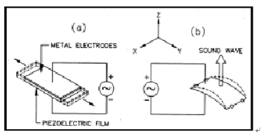
Unlike piezoelectric ceramic sensors, the piezoelectric film sensor has a wide dynamic range and is wide-band. The broadband characteristics (close to DC to 2GHz) and low Q values are partly attributable to the flexibility of the polyester. When used as a microphone, the curved piezoelectric film device is fixed at both ends and vibrate in the length (d31) mode, as shown in Figure 10. A piezoelectric film is a high fidelity loudspeaker. It can also be used as a new speaker in toys, inflatable items and game tools. The d31 mode (Figure 10) can also be used in the air for ultrasonic ranging, with a frequency of about 50kHz.
When used as a high frequency ultrasonic transmitter (general >500KHz), a piezoelectric film usually works in a thickness (d33) mode. The maximum transmission occurs when the thickness is resonant. The piezoelectric film 28 m basic half wavelength resonant frequency is about 40MHz:
|